Resolving Floating Neutral and 410 kVA AVR Installation
THE CHALLENGE
Resolving Floating Neutral and Severe Grid Instability
Persistent power instability, severe voltage drops, and frequent system trips can cripple the operations of any major facility. When a leading university campus began experiencing widespread malfunctions of sensitive computer electronics, constant tripping of backup UPSs and inverters, and overstrained motors, they knew they had a critical problem.
Because of these constant, unpredictable outages, the failure rate of computer power supplies was exceptionally high. Consequently, staff productivity was severely degraded across the campus.
Before any physical hardware was upgraded, a precise, data-driven diagnosis was required. Ultimately, this critical first step allowed our team to focus on the core engineering challenges: resolving floating neutral hazards and stabilizing the incoming grid.
⚠️ “The university’s highly sensitive server room was experiencing critical equipment restarts because their backup UPS systems simply could not cope with the wildly distorted phase voltages.”
PHASE 1: DIAGNOSTICS
The Power Quality Audit & Load Profiling
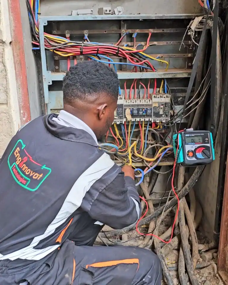
To establish a critical baseline, our team initiated a 5-day logging session at the university’s main switchboard during peak operational hours. Operating in full insulated PPE, our highly trained technicians executed live connections directly to exposed busbars. Consequently, they safely installed the monitoring equipment without disrupting the university’s daily activities.
The Fluke 3540FC meticulously recorded peak power consumption, voltage fluctuations, and power factor. All critical measurements were logged continuously and accessed remotely via cloud analytics, providing our engineering team with 24/7 system visibility.
PHASE 2: THE DISCOVERY
Uncovering a Dual-Threat Hazard
Our continuous monitoring and rigorous physical inspections uncovered two catastrophic issues compounding one another.
Threat 1: Critical Grid Voltage Dips
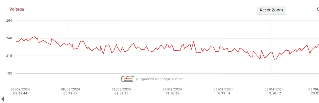
During our baseline audit, data loggers captured a severe issue with the incoming KPLC grid supply. Incoming voltages were volatile, swinging from highs of 250VAC during off-peak hours down to 220VAC during peak operational hours. Furthermore, this supply was punctuated by random, severe dips crashing to a critical 210VAC.
Once factored in with the natural voltage drop across the university’s expansive internal distribution network, the voltage reaching the actual end-user equipment was critically low.
Threat 2: The "Silent Killer" – A Floating Neutral
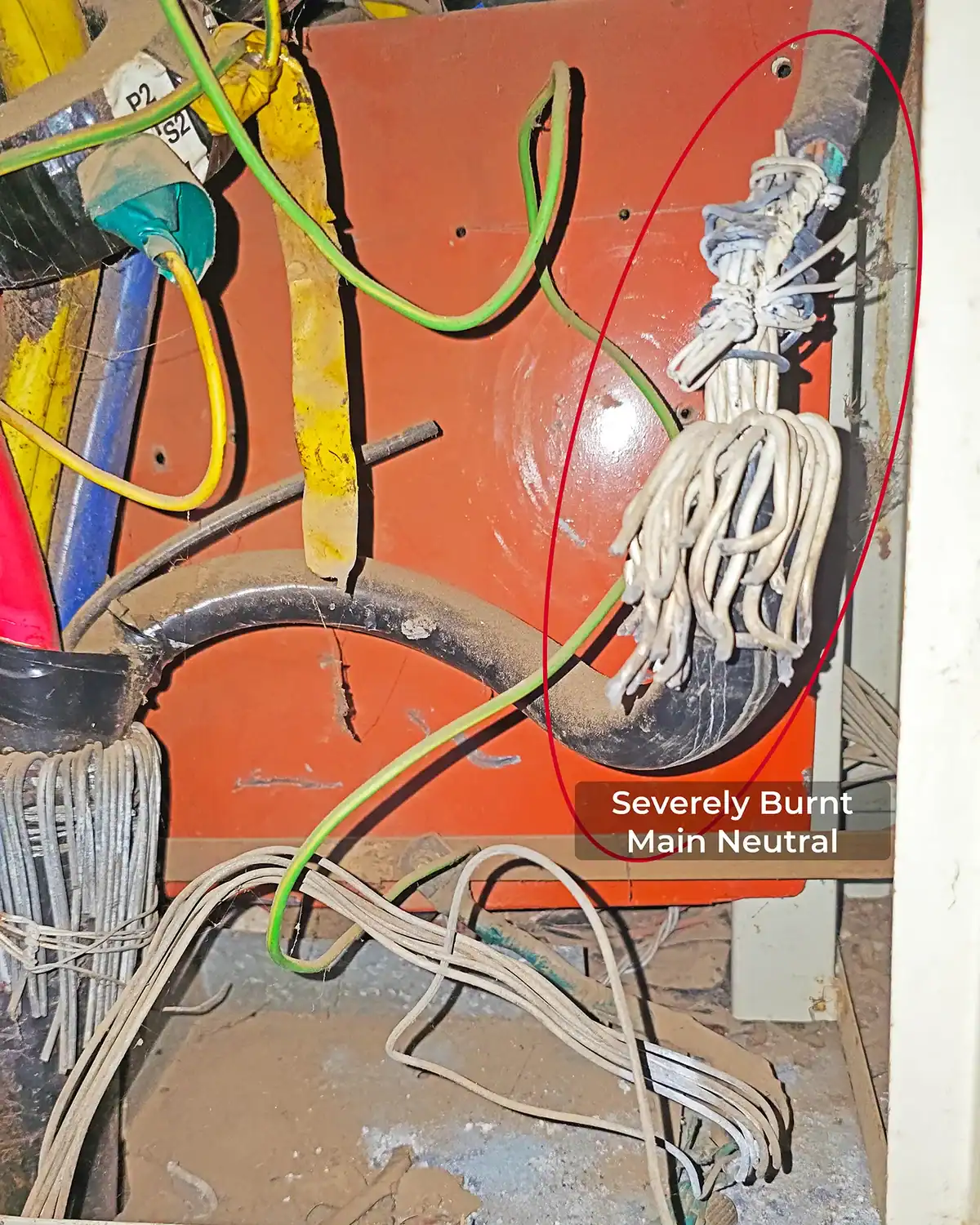
While the data loggers captured the grid dips, our physical inspection uncovered an equally catastrophic hazard at the source: a severely burnt, loose Main Incoming Neutral termination.
In any real-world 3-phase installation, you cannot perfectly control which line draws how much current. This creates an “out of balance” current. Ideally, the main neutral wire carries this leftover current safely back to the supply. As a result, the system’s star point remains anchored safely at 0V.
However, when a main neutral termination burns and disconnects, that vital return path is choked off. This creates a terrifying and destructive electrical scenario known as a “Floating Neutral”:
- The Star Point Shifts: Because the out of balance current can no longer return via the neutral, it is forced to return through the phase lines, violently shifting the star point away from 0V.
- Voltages Seesaw: Voltage and current shift uncontrollably. As a result, lightly loaded phases get destructive overvoltages that damage electronics, while heavily loaded phases experience severe brownouts.
PHASE 3: EXECUTION
The Rectification & Engineered Solution
To permanently resolve these hazards, a superficial cleanup wasn’t enough. The Enginnovat team designed and executed a comprehensive, two-part infrastructure upgrade:
1. Resolving Floating Neutral Hazards
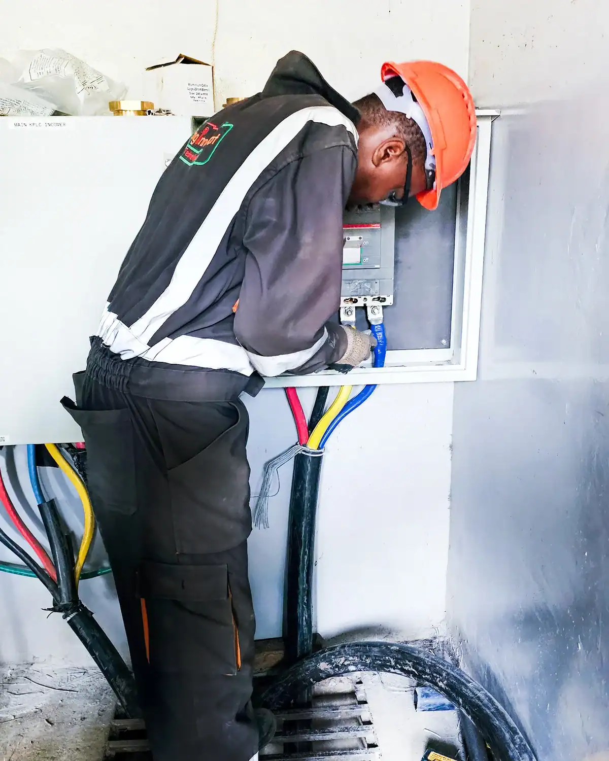
Our team stripped back the heat-damaged cables and re-terminated them with brand-new, heavy-duty lugs. We then firmly connected the incoming main power supply to a newly installed motorized main breaker. This guaranteed rock-solid, zero-resistance terminations across the board.
By entirely removing the compromised, heat-stressed part and establishing a pristine contact surface, we eliminated the localized heating that originally caused the neutral to fail. As a result, we restored true balance to the 3-phase system.
Furthermore, the integration of a new motorized main breaker drastically elevates the facility’s operational safety. This advanced switchgear provides superior overcurrent protection. Its built-in motorized automation also allows for rapid fault isolation and seamless synchronization with the heavy-duty stabilization hardware we deployed downstream.
2. Installing the 410 kVA AVR & PFC System
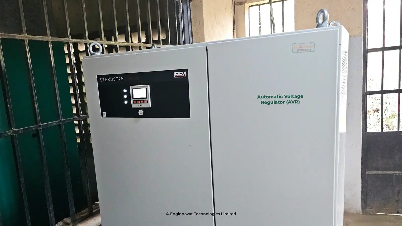
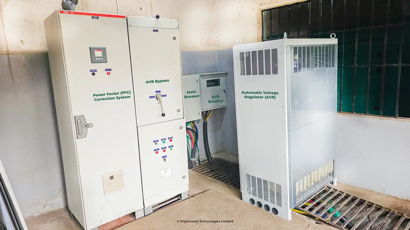
Based on our undeniable metrics, we successfully supplied, installed, and commissioned a heavy-duty IREM 410 kVA Automatic Voltage Regulator (AVR) directly at the university’s main incomer. Following this, we integrated a robust Power Factor Correction (PFC) system.
The primary function of this AVR is to actively stabilize the erratic incoming grid supply. Consequently, it guarantees a constant, safe output of 240VAC on each phase.
PHASE 4: VERIFICATION
Long-Term Tracking & Results
As engineers, we don’t just install; we verify. For our long-term post-installation analysis, we implemented a highly efficient and integrated monitoring approach. Specifically, we tracked the AVR’s continuous output remotely via the VRM Cloud Portal. This enabled us to pull live data directly from the nearest Victron Multiplus II inverter, located 100m downstream from the main switchboard.
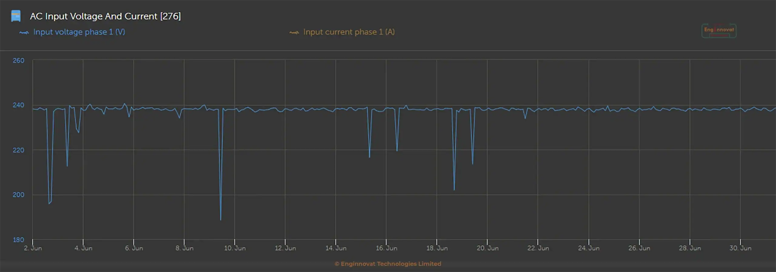
The 30-Day Voltage Log Proves:
- A beautifully flat, stabilized curve averaging 238VAC on each phase. (The tiny 2V difference from the target 240VAC perfectly accounts for the expected voltage drop across the 100m cable run).
- Complete elimination of the damaging 210VAC sags and the 250VAC overvoltages.
Note: The sharp, momentary drops to 0V on the graph represent complete KPLC grid blackouts, not voltage dips.
By stabilizing the power at the source and securing the main terminations, we successfully eliminated cascading equipment failures, protected sensitive electronics, and secured the university’s long-term infrastructure investment.
Share this Case Study
YOUR ICT & POWER EXPERTS
Stop Guessing. Start Engineering.
You can invest in the best power stabilization hardware in the world, but if your main terminations are failing, your equipment will still burn. Secure your facility today with a professionally audited and designed electrical system.